定位 (GNSS)
QField可以使用内置的GNSS (全球导航卫星系统,如GPS、格洛纳斯、伽利略或北斗)。QField还可以通过 NMEA streams over Bluetooth、TCP 或 UDP connection 连接到外部天线。
GNSS设备还能够测量地球表面上当前2D位置附近的高程。
可视化
激活定位后,您的位置将在地图上显示为蓝色。如果静止不动,将显示为蓝色圆点;如果正在移动,则显示为指示移动方向的箭头。
如果设备具有内置指南针功能,蓝色信号射束表示设备的当前方向。
当前位置周围的圆圈表示定位设备报告的精度。
配置
QField设置的定位选项卡中提供了以下设置。
测量 (M) 值
将几何图形数字化到包含M维度的矢量图层时,每当坐标光标锁定到当前位置时,QField就会向各个顶点添加测量值。
默认情况下,该值将表示捕获位置的时间戳 (从Unix时间戳开始的毫秒数)。您可以使用设置的定位选项卡中的组合框更改此值。
可选择的可用值包括时间戳、对地速度、方位角、水平精度和垂直精度以及PDOP、HDOP和VDOP。
精度要求
可以定义所需最小测量精度。品质将报告为三个等级,即差 (红色)、良 (黄色) 和优 (绿色)。这些颜色显示在GNSS按钮顶部的一个点。
可以在设置的定位选项卡中定义阈值。
如果 启用精度限制模式 设置为激活状态,您将无法在坐标光标锁定到当前位置且精度值较差 (红色) 的情况下采集新的测量值。
天线高度修正
使用中的天线杆高度可在设置中定义。任何测量的海拔高度都将通过该值进行校正。
海拔校正/垂直网格偏移
海拔值可以用垂直网格偏移文件进行校正,以计算正交高度。
Vertical grid shift files have to be made available to QField by putting them into the QField app folder [App Directory]/QField/proj.
一旦把网格偏移文件放到此处,将在QField中的 使用中的垂直网格偏移 下的 定位设置 可用。
如果您正在使用海拔校正,并且使用了外部定位设备,请考虑关闭 使用设备的垂直海拔 。
当前支持的格式有:
- GeoTIFF (.tif, .tiff)
- NOAA Vertical Datum (.gtx)
- NTv2 Datum Grid Shift (.gsb)
- Natural Resources Canada's Geoid (.byn)
Example: Netherlands - ETRS89 to NAP
For transformations involving the Dutch NAP (Normaal Amsterdams Peil) vertical datum, you'll need the official grid file from NSGI.
-
Download the file: Get
nlgeo2018.gtxdirectly from the NSGI website. -
Place the downloaded
.gtxfile into the directory [App Directory]/QField/proj. This is independent of whether you are using QFieldCloud or not.
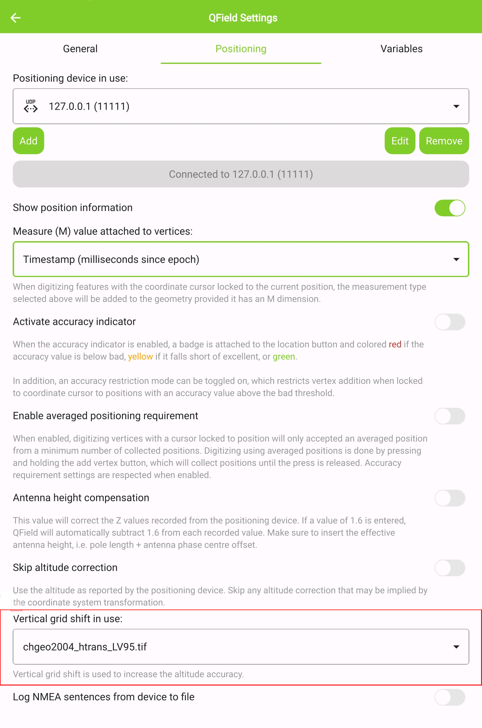
Example: Switzerland - CH1903+/LV95
To get precise altitude data for Cadastral Surveying in Switzerland (LV95), you must use the geoid correction grid from Swisstopo.
The official file comes in an .agr format and must be converted to .gtx (NTv2 Grid Shift File) before it can be used.
Other raster formats like (.tiff) can also be used
-
Download the "Geoid OGD" dataset from Swisstopo under the following link Download Link: Geoid OGD from Swisstopo.
-
Unzip the archive to retrieve the file:
chgeo2004_htrans_LV95.agr. -
Convert the file using the using the gdal_translate algorithm with one of the following options:
Method 1: QGIS Graphical User Interface (GUI)
-
In QGIS, open the Processing Toolbox panel.
-
Navigate to GDAL > Raster conversion > Translate (Convert format) tool.
-
Configure it with your needed requirements:
-
Input layer: Select your
chgeo2004_htrans_LV95.agrfile. -
Output file: Click "Save to File..." and name your output file with a
.gtxextension (or other format needed), for example,chgeo2004_htrans_LV95.gtx.
-
-
Click Run. The other default settings are typically sufficient for this conversion.
![]()
Method 2: Command Line (qgis_process)
For automation or users who prefer the command line, qgis_process is a great option.
- Open your terminal and run the following command, adjusting the paths to your files.
qgis_process run gdal:translate --INPUT="/path/to/your/chgeo2004_htrans_LV95.agr" --OUTPUT="/path/to/your/chgeo2004_htrans_LV95.gtx"
Method 3: PyQGIS Script
You can also perform the conversion programmatically within the QGIS Python Console or a standalone script.
import processing

input_grid = '/path/to/your/chgeo2004_htrans_LV95.agr'
output_grid = '/path/to/your/chgeo2004_htrans_LV95.gtx'

processing.run("gdal:translate", {
    'INPUT': input_grid,
    'OUTPUT': output_grid
})

print(f"Successfully converted grid to: {output_grid}")
QField界面
-
Copy the
chgeo2004_htrans_LV95.gtxfile to the directory [App Directory]/QField/proj on your mobile device. -
Under the QField settings, select the file as the vertical grid shift correction file: Main menu > three dots > Settings > Positioning
-
Enanble your GNSS device. it will directly center to your current location once the positioning information is available.
-
Change to edit mode and press on the target button - the cross in the center means it is using GNSS positioning.
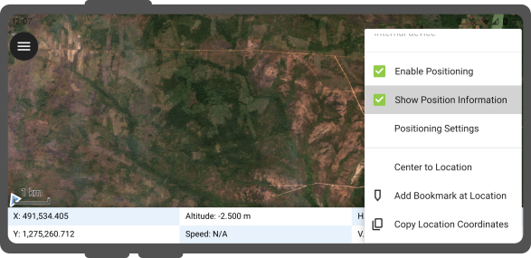
A long press on the GNSS button will show the positioning menu.
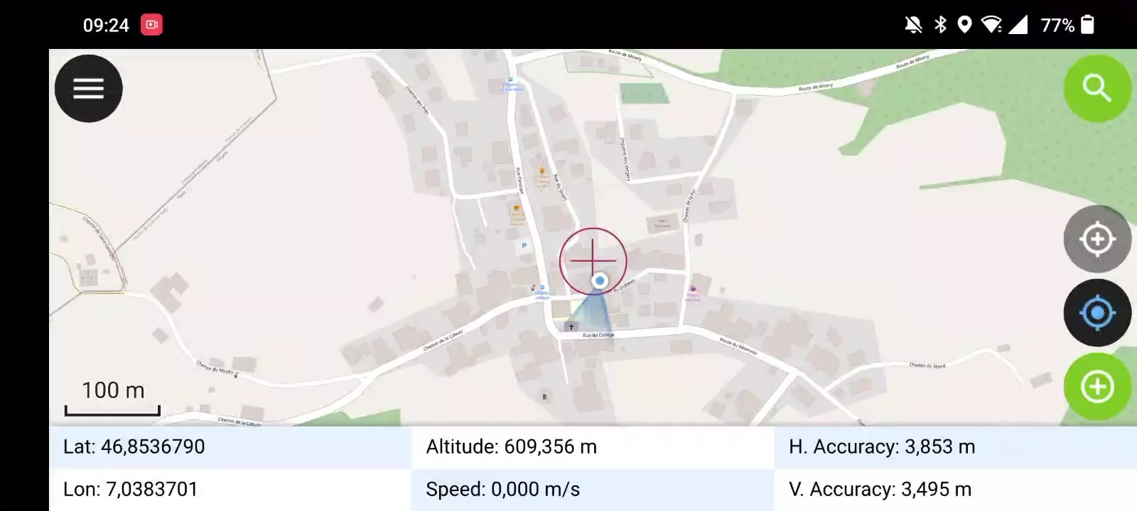
Inside the menu you can turn on the Show position information which will show the current coordinates that are reprojected into the CRS of your project along with the precision information.
笔记
如果您在工程CRS中看到 WGS 84 纬度/经度信息而不是就得信息,那么您可能设备没有信号。
使用外部GNSS接收机
QField界面
QField支持经由NMEA数据流通过蓝牙、TCP 或 UDP connections 连接到外部GNSS定位设备。
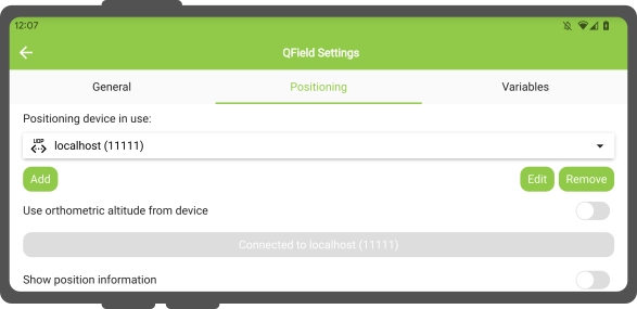
In Settings > Positioning, you are able to manage and swithch between your internal and saved external GNSS devices.
平台支持的连接细分如下:
| Android | iOS | Windows | Linux | MacOS | |
|---|---|---|---|---|---|
| 蓝牙 | * | ||||
| TCP | |||||
| UDP | |||||
| 串行端口 |
- (*) Windows的蓝牙支持通过操作系统连接到GNSS设备时自动创建的虚拟串行端口来实现。 *
The NMEA sentences currently supported are GGA, RMC, GSA, GSV, GST, VTG, HDG and HDT.
笔记
请确保没有其他类似模拟位置提供商的应用程序使用相同的连接。
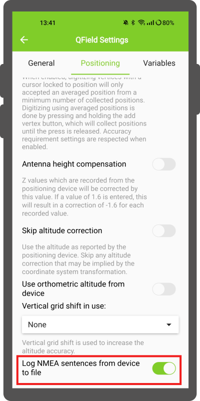
外部接收器日志
In Settings > Positioning if you have selected an external receiver as the positioning device, you will find a switch Log NMEA sentences from device to file.
If this is activated, all NMEA sentences coming from external positioning devices will be logged to a file.
The logs will be placed in [App Directory]/QField/logs.
笔记
请注意,如果日志始终处于打开状态,将填满所有存储空间。
模拟位置
QField界面
可以通过不同的安卓应用程序向QField提供模拟位置。在此有几个选项,其中之一是 Android NTRIP 客户端 。
要使用此功能,您必须 在安卓设备上启用模拟位置 。
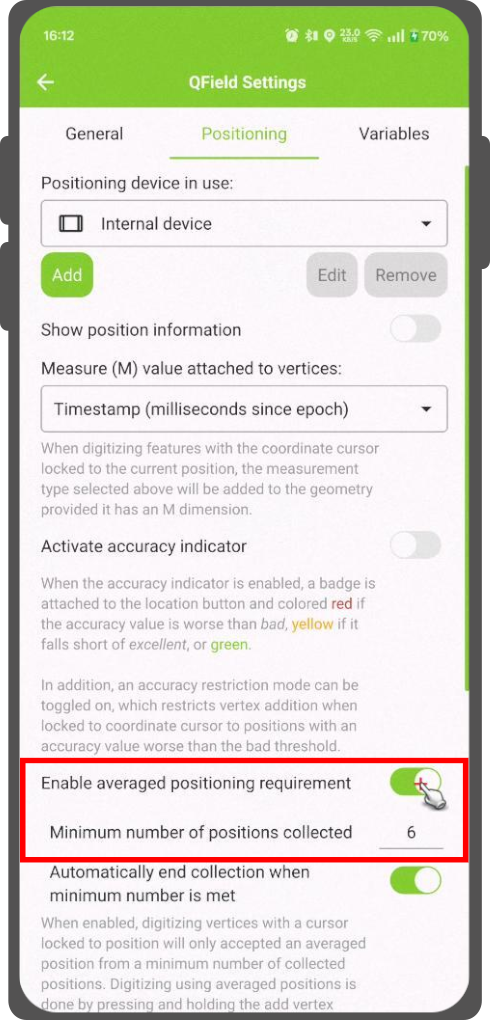
平均定位功能
QField界面
笔记
必须通过 锁定到位置按钮 将坐标光标锁定到当前位置
有一个功能允许您使用平均位置进行数字化。
按住添加顶点按钮开始测量,该按钮将开始收集位置信息。
During the collection, an indicator will appear on top of the coordinate cursor showing the number number of the collected positions. If an averaged position minimum count requirement is active, a progress bar will also be present indicating the progress towards meeting that requirement.
- To activate direct to side "Dashboard" > Settings > Positioning
- Shortly tap where you want to collect points and QField will automatically add the averaged position once the minimum count is met.
Note
When using @gnss_* or @position_ variables on averaged positions, the variable will also represent the average over all collected samples.
定位变量
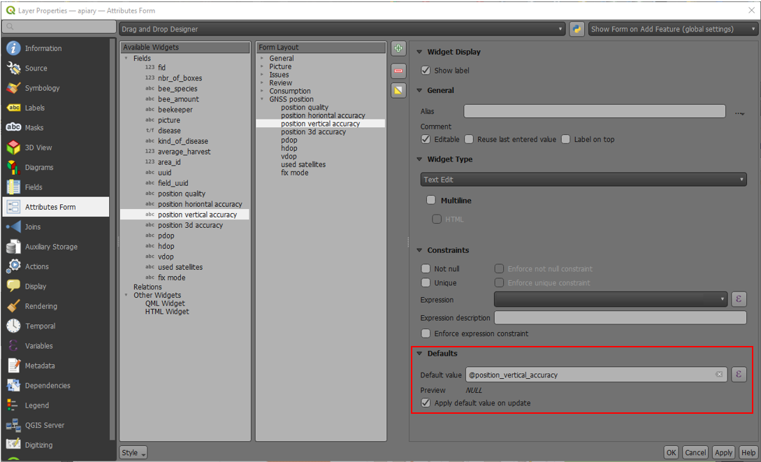
You can get the positioning information both of your internal and external device by specifically configuring your attribute form.
These variables are commonly used as part of default values expressions for fields to keep track of the quality of individual measured points.
A common use case is recording the horizontal accuracy, which can be done by using the variable @position_horizontal_accuracy.
Another often used strategy is using the altitude of the current measurement which can be achieved with z(@position_coordinate).
For a complete listing of all available variables, refer to the expression variables reference documentation.
Information for GNSS Z value with Vertical grid shift in use: - Antenna height compensation=False
| Vertical Grid Shift in use | point Z Value z(geometry) | GNSS Device z(@position_coordinate) | QField Display | QField Label |
|---|---|---|---|---|
| None | Z ellipsoidal device value | Z ellipsoidal device value | Z ellipsoidal device value | Altitude: xxx.xxxx m |
| Orthometric from device | Z orthometric device value | Z orthometric device value | Z orthometric device value | Altitude: xxx.xxxx m (ortho.) |
| USER_Shift_Grid.GTX vertical grid shift |
Z shiftgrid value | Z ellipsoidal device value | Z shiftgrid value | Altitude: xxx.xxxx m (grid) |
Vertex log layer
It is good practice to create a log layer of the collected vertices. It enables you to keep track of the meta data for each vertex like GNSS quality attributes and more.
Setup
-
Add a point layer to the project and attributes configured to store this information.
-
Assign the role digitizing logger to a point layer.
-
Go to > Project > Properties... > QField.
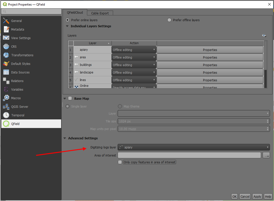
-
Set default values to the attributes using the positioning variables mentioned above.