Poziționare (GNSS)
QField can make use of the internal GNSS (Global Navigation Satellite System, like GPS, GLONASS, Galileo or Beidou). QField can also connect to external antennas through NMEA streams over Bluetooth, TCP, or UDP connection.
GNSS devices are also capable of measuring the altitude next to the current 2D position on the earth surface.
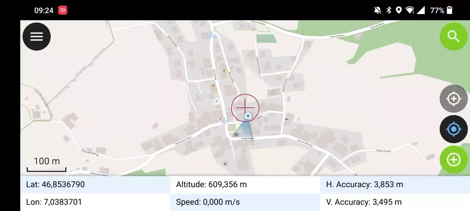
Visualization
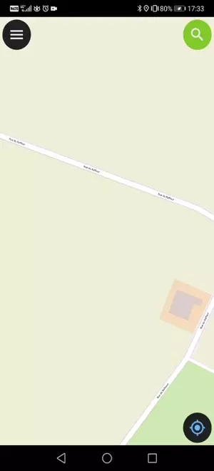
When positioning is activated, your position will be shown in blue on the map. Your location is visible either as a blue dot if you are still or as an arrow indicating your movement direction if you are moving.
The blue beam indicates the current orientation of your device if the device has a builtin magnetic compass.
A circle around your current position indicates the precision as reported by the positioning device.
Configurare
The following settings are available in QField settings' positioning tab.
Measure (M) value
When digitizing a geometry onto a vector layer that contains an M dimension, QField will add a measurement value to individual vertices whenever the coordinate cursor is locked to the current position.
By default, the value will represent the captured position's timestamp (milliseconds since epoch). You can change this value using the combo box in the settings' positioning tab.
The available values to chose from are timestamp, ground speed, bearing, horizontal accuracy and vertical accuracy as well as PDOP, HDOP and VDOP.
Accuracy requirement
A minimum desired accuracy for measurements can be defined. The quality will be reported in three classes, bad (red), ok (yellow) and excellent (green). These colors will show up as a dot on top of the GNSS button.
The thresholds can be defined in the settings' positioning tab.
If the Enable accuracy requirement setting is activated, you will not be able to collect new measurements with the coordinate cursor locked to the current position with an accuracy value which is bad (red).
Antenna height compensation
The height of the antenna pole in use can be defined in the settings. Any measured altitude will be corrected by this value.
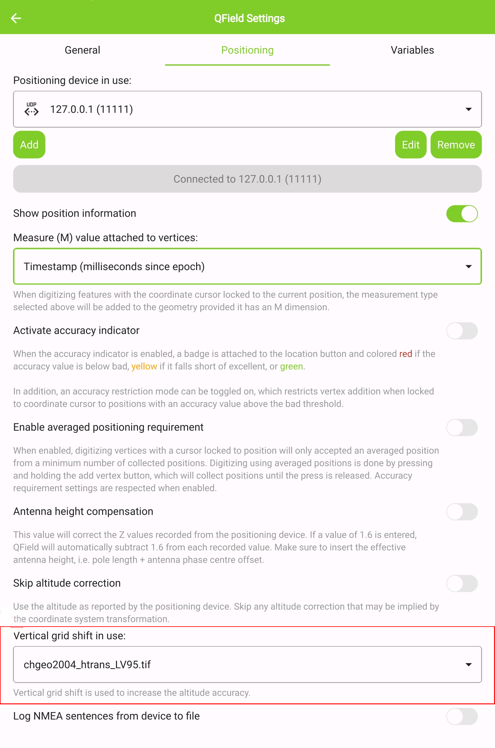
Altitude correction / vertical grid shift
Altitude values can be corrected with vertical grid shift files to calculate orthometric height.
Vertical grid shift files have to be made available to QField by putting
them into the QField app folder <drive>:/Android/data/ch.opengis.qfield/files/QField/proj.
Once the grid shift file is placed there, it is available in QField in the Positioning settings under Vertical grid shift in use.
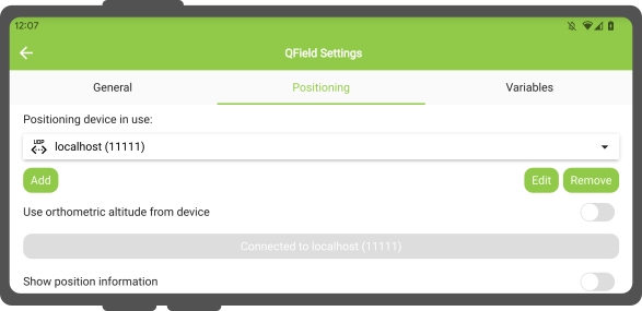
If you are using altitude correction and an external positioning device is used, consider turning Use orthometric altitude from device off.
The formats currently supported are:
- GeoTIFF (.tif, .tiff)
- NOAA Vertical Datum (.gtx)
- NTv2 Datum Grid Shift (.gsb)
- Natural Resources Canada's Geoid (.byn)
For example: For the transformation from ETRS89 (reference ellipsoid GPS) to NAP (Dutch) users can download the file nlgeo2018.gtx from NSGI and put it in the directory.
To obtain precise altitude data for Cadastral Surveying in Switzerland, users can access the file correction of the vertical grid shift through Geoid OGD from Swisstopo.
Following the download, users are advised to perform a conversion of the file labeled chgeo04_htrans_lv95.agr to chgeo04_htrans_lv95.gtx.
The QGIS processing algorithm gdal:translate (convert format) can be used for that.
Utilizare
Fieldwork
A short press on the GNSS button will turn on the GNSS and center to the current location once positioning information is available.
Activate edit mode and press on the target button, the cross in the center means it is using GNSS positioning.
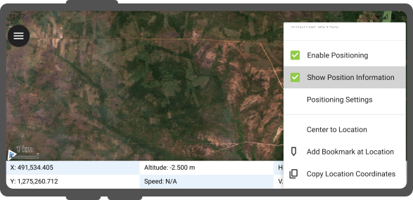
A long press on the GNSS button will show the positioning menu.
Inside the positioning menu you can turn on the Show position information which will show the current coordinates which are reprojected into the project CRS along with precision information.
Note
If you see WGS 84 lat/lon information instead of information in your project CRS, you probably have no signal yet.
Using an external GNSS Receiver
Fieldwork
QField supports connecting to external GNSS positioning devices via NMEA streams through Bluetooth, TCP, or UDP connections.
In Settings > Positioning, you can find a set of buttons to add, edit, or delete external devices as well as a dropdown list to switch between internal and saved external GNSS devices.
The breakdown of connections support by platform is as follow:
| Android | iOS | Windows | Linux | MacOS | |
|---|---|---|---|---|---|
| Bluetooth | * | ||||
| TCP | |||||
| UDP | |||||
| Serial port |
(*) Bluetooth support on Windows occurs through the virtual serial port automatically created by the operating system when it connects to the GNSS device.
The NMEA sentences currently supported are GGA, RMC, GSA, GSV, GST, VTG, HDG and HDT.
Note
Make sure no other app like mock location providers are using the same connection.
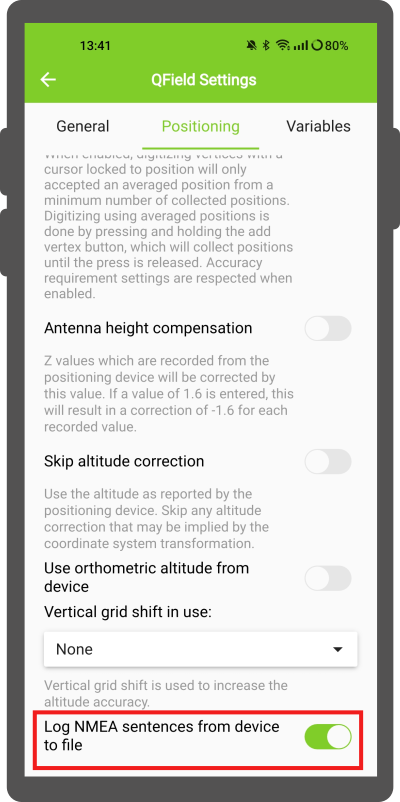
External receiver log
In Settings > Positioning if you have selected an external receiver as the positioning device, you will find a switch Log NMEA sentences from device to file. If this is activated, all NMEA sentences coming from external positioning devices will be logged to a file.
The logs will be placed in Android/data/ch.opengis.qfield/files/QField/logs.
Note
Be aware that if the log is always turned on, it will fill up all the storage.
Mock location
Fieldwork
It is possible to provide a mock location via a separate android app to QField. There are several options for this, one of them is Android NTRIP Client.
To use this you have to enable mock locations on your Android device.
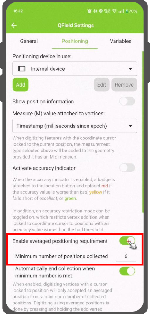
Averaged positioning functionality
Fieldwork
Note
The coordinate cursor must be locked to the current location via the Lock to position button
There is a function that allows you to digitize using averaged positions.
The survey will start by pressing and holding the add vertex button, which will start collecting positions.
While collecting, an indicator will appear on top of the coordinate cursor showing a text reflecting the current number of collected positions. If an averaged position minimum count requirement is active, a progress bar will also be present indicating the progress towards meeting that requirement.
The setting to activate an average position minimum count threshold can be found in QField settings's positioning panel. When active, holding the add vertex button is not required, a short tap on the button will begin the collection of positions and automatically add the averaged position when the minimum count requirement is met.
When using @gnss_* or @position_ variables on averaged positions, the variable will also represent the average over all collected samples.
Project configuration
Desktop preparation
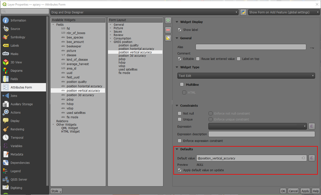
Positioning variables
You can get access to positioning information through additional expression variables accessible in the attribute form. These will only be available when positioning is enabled.
These variables are commonly used as part of default values expressions for fields to keep track of the quality of individual measured points.
A common use case is recording the horizontal accuracy, which can be done by using the variable @position_horizontal_accuracy.
Another often used strategy is using the altitude of the current measurement which can be achieved with z(@position_coordinate).
For a complete listing of all available variables, refer to the expression variables reference documentation.
Information for GNSS Z value with Vertical grid shift in use: - Antenna height compensation=False
| Vertical Grid Shift in use | point Z Value z(geometry) | GNSS Device z(@position_coordinate) | QField Display | QField Label |
|---|---|---|---|---|
| None | Z ellipsoidal device value | Z ellipsoidal device value | Z ellipsoidal device value | Altitude: xxx.xxxx m |
| Orthometric from device | Z orthometric device value | Z orthometric device value | Z orthometric device value | Altitude: xxx.xxxx m (ortho.) |
| USER_Shift_Grid.GTX vertical grid shift |
Z shiftgrid value | Z ellipsoidal device value | Z shiftgrid value | Altitude: xxx.xxxx m (grid) |
Vertex logger
It is possible to setup a log layer of the collected vertices. This allows to keep track of meta data for each vertex like GNSS quality attributes and more. To set this up, a point layer can be added to the project and attributes configured to store this information.
Then you should assign the role digitizing logger to a point layer.
Go to QFieldSync > Project Properties
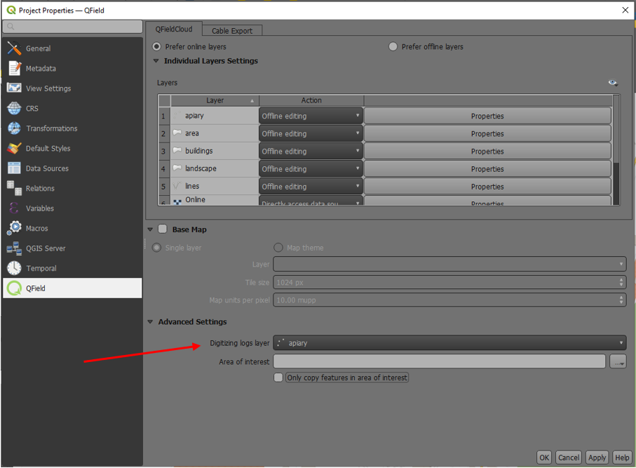
To be most effective, the layer attributes should have default values that relies on the positioning variables enumerated above.