Posicionamento (GNSS)
O Qfield consegue usar o sistema interno GNSS (Sistemas de Satélites Globais de Navegação, como GPS, GLONASS, Galileo ou Beidou). QField também consegue ligar a antenas externas através de NMEA usando ligações Bluetooth, TCP, ou UDP.
Dispositivos GNSS são também capazes de medir a altitude perto da posição 2D atual na superfície da terra.
Visualização
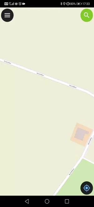
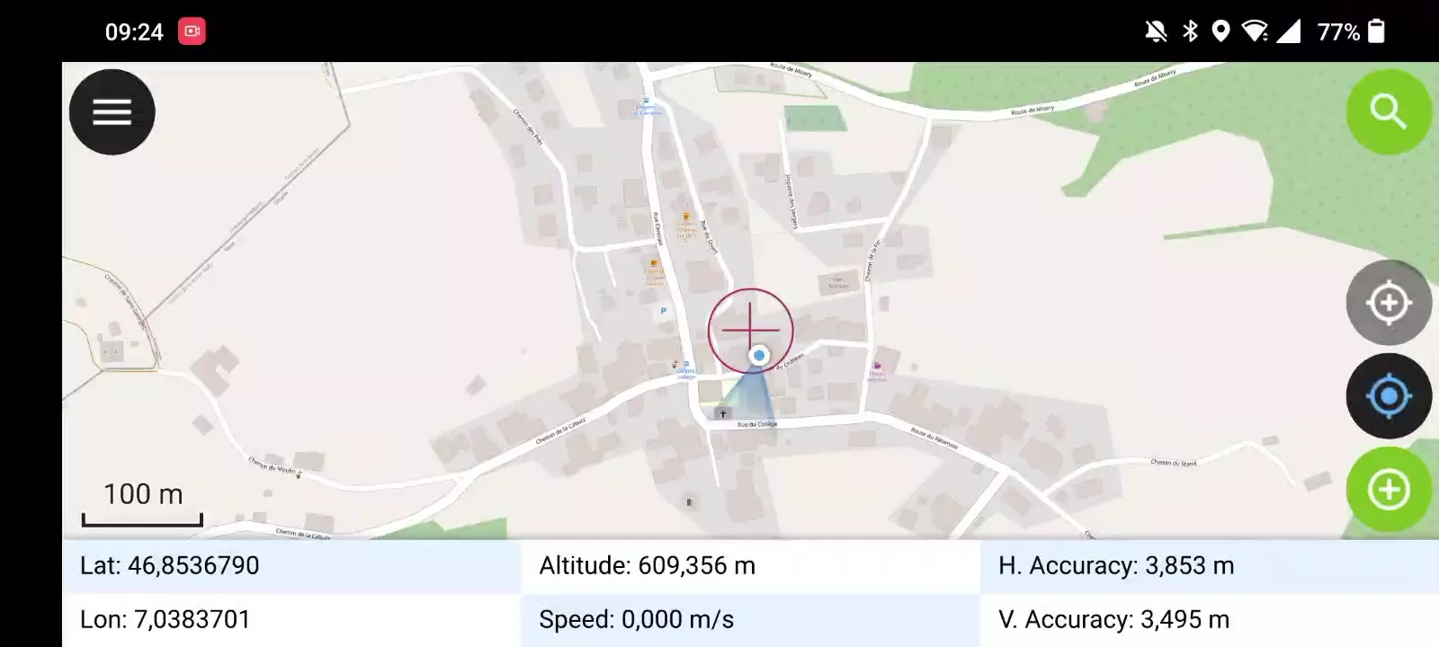
Quando o posicionamento estiver ativado, a sua posição será mostrada com a cor azul no mapa. A sua localização é visível como um ponto azul se você estiver parado ou como uma seta a indicar a direção do seu movimento se estiver a movimentar.
O raio azul indica a orientação atual do seu dispositivo se o seu dispositivo tiver um compasso magnético interno.
Um círculo à volta da posição atual indica a precisão reportada pelo dispositivo de posicionamento.
Configuração
As configurações seguintes encontram-se disponíveis no separador Posicionamento das configurações do QField.
Mede o valor (M)
Ao digitalizar uma geometria numa camada vetorial que contém uma dimensão M, o QField adicionará um valor de medição aos vértices individuais sempre que o cursor de coordenadas está bloqueado na posição atual.
Por padrão, o valor representará o timestamp da posição capturada (milissegundos desde Epoch). Podes alterar este valor com a caixa de valores no separador de posicionamento das configurações.
Os valores disponíveis para escolha são data/hora, velocidade, orientação, precisão horizontal e precisão vertical, bem como PDOP, HDOP e VDOP.
Requirimentos de precisão
Uma precisão mínima desejada para medições pode ser definida. A qualidade será relatada em três classes, mau (vermelho), ok (amarelo) e excelente (verde). Estas cores aparecerão como um ponto no topo do botão GNSS.
Os limites podem ser definidos no separador do posicionamento nas configurações.
Se a configuração Ativar requisito de precisão estiver ativada, não poderá recolher novas medições com o cursor bloqueado na posição atual com um valor precisão baixo (vermelho).
Compensação da altura da antena
A altura do poste da antena em uso pode ser definido nas configurações. Qualquer altitude medida irá ser corrigida por este valor.
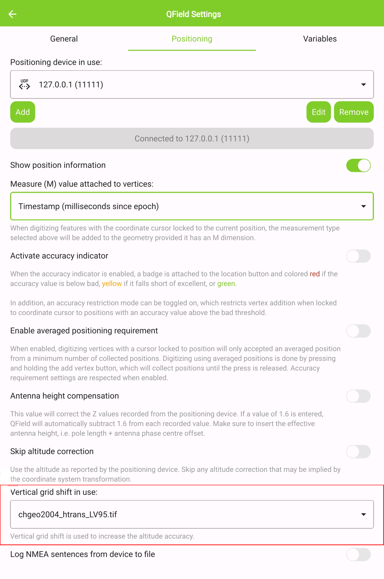
Correção de altitude / grelha de transformação vertical
Os valores de altitude podem ser corrigidos com ficheiros de grelhas de transformação vertical para calcular a altura ortométrica.
Vertical grid shift files have to be made available to QField by putting them into the QField app folder [App Directory]/QField/proj.
Quando o ficheiro da grelha de deslocamento é colocado lá, ele fica disponível no QField nas Definições de Posicionamento em Deslocamento vertical da grelha em uso.
Se estás a usar correção de altitude e um dispositivo externo de localização está em uso, considera desligar Utilize a altitude ortométrica do dispositivo.
Os formatos atualmente suportados são:
- GeoTIFF (.tif, .tiff)
- NOAA Vertical Datum (.gtx)
- NTv2 Datum Grid Shift (.gsb)
- Natural Resources Canada's Geoid (.byn)
Example: Netherlands - ETRS89 to NAP
For transformations involving the Dutch NAP (Normaal Amsterdams Peil) vertical datum, you'll need the official grid file from NSGI.
-
Download the file: Get
nlgeo2018.gtxdirectly from the NSGI website. -
Place the downloaded
.gtxfile into the directory [App Directory]/QField/proj. This is independent of whether you are using QFieldCloud or not.
Example: Switzerland - CH1903+/LV95
To get precise altitude data for Cadastral Surveying in Switzerland (LV95), you must use the geoid correction grid from Swisstopo.
The official file comes in an .agr format and must be converted to .gtx (NTv2 Grid Shift File) before it can be used.
Other raster formats like (.tiff) can also be used
-
Download the "Geoid OGD" dataset from Swisstopo under the following link Download Link: Geoid OGD from Swisstopo.
-
Unzip the archive to retrieve the file:
chgeo2004_htrans_LV95.agr. -
Convert the file using the using the gdal_translate algorithm with one of the following options:
Method 1: QGIS Graphical User Interface (GUI)
-
In QGIS, open the Processing Toolbox panel.
-
Navigate to GDAL > Raster conversion > Translate (Convert format) tool.
-
Configure it with your needed requirements:
-
Input layer: Select your
chgeo2004_htrans_LV95.agrfile. -
Output file: Click "Save to File..." and name your output file with a
.gtxextension (or other format needed), for example,chgeo2004_htrans_LV95.gtx.
-
-
Click Run. The other default settings are typically sufficient for this conversion.
![]()
Method 2: Command Line (qgis_process)
For automation or users who prefer the command line, qgis_process is a great option.
- Open your terminal and run the following command, adjusting the paths to your files.
qgis_process run gdal:translate --INPUT="/path/to/your/chgeo2004_htrans_LV95.agr" --OUTPUT="/path/to/your/chgeo2004_htrans_LV95.gtx"
Method 3: PyQGIS Script
You can also perform the conversion programmatically within the QGIS Python Console or a standalone script.
import processing

input_grid = '/path/to/your/chgeo2004_htrans_LV95.agr'
output_grid = '/path/to/your/chgeo2004_htrans_LV95.gtx'

processing.run("gdal:translate", {
    'INPUT': input_grid,
    'OUTPUT': output_grid
})

print(f"Successfully converted grid to: {output_grid}")
Trabalho de campo
-
Copy the
chgeo2004_htrans_LV95.gtxfile to the directory [App Directory]/QField/proj on your mobile device. -
Under the QField settings, select the file as the vertical grid shift correction file: Main menu > three dots > Settings > Positioning
-
Enanble your GNSS device. it will directly center to your current location once the positioning information is available.
-
Change to edit mode and press on the target button - the cross in the center means it is using GNSS positioning.
A long press on the GNSS button will show the positioning menu.
Inside the menu you can turn on the Show position information which will show the current coordinates that are reprojected into the CRS of your project along with the precision information.
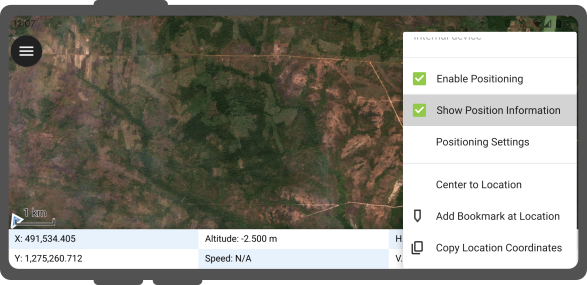
Nota
Se vês informação WGS 84 lat/lon ao invés da informação do SRS do teu projeto, provavelmente ainda não tens sinal.
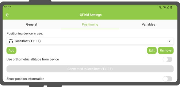
Usar um Receptor externo GNSS
Trabalho de campo
O QField suporta a ligação com dispositivos de posicionamento GNSS externos via NMEA através de Bluetooth, TCP, ou conexões UDP.
In Settings > Positioning, you are able to manage and swithch between your internal and saved external GNSS devices.
O tipo de ligações suportadas por plataforma é a seguinte:
| Android | iOS | Windows | Linux | MacOS | |
|---|---|---|---|---|---|
| Bluetooth | * | ||||
| TCP | |||||
| UDP | |||||
| Porta de série |
() O suporte Bluetooth no Windows ocorre automaticamente através da porta virtual criado pelo sistema operativo quando se liga ao dispositivo GNSS.*
The NMEA sentences currently supported are GGA, RMC, GSA, GSV, GST, VTG, HDG and HDT.
Nota
Certifique-se que não tem outra aplicação com fornecedores de mock location a usar a mesma ligação.
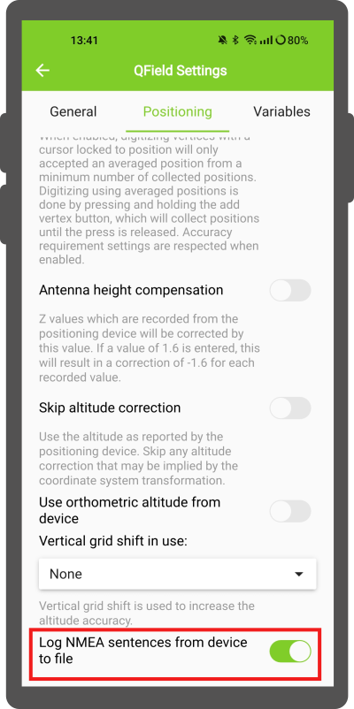
External receiver log
In Settings > Positioning if you have selected an external receiver as the positioning device, you will find a switch Log NMEA sentences from device to file.
If this is activated, all NMEA sentences coming from external positioning devices will be logged to a file.
The logs will be placed in [App Directory]/QField/logs.
Note
Be aware that if the log is always turned on, it will fill up all the storage.
Localização simulada
Trabalho de campo
É possível fornecer um mock location através de uma aplicação Android que é separado do QField. Existem várias opções para isso, uma delas é Android NTRIP Client.
Para usar este opção terá de ativar mock locations no dispositivo Android.
Funcionalidade de cálculo de posicionamento médio
Trabalho de campo
Note
The coordinate cursor must be locked to the current location via the Lock to position button
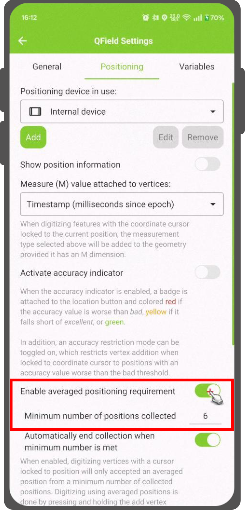
Existe uma função que permite digitalizar usando o cálculo de posições médias.
O levantamento começará pressionando e segurando o botão de adicionar vértice, que começará a recolher posições.
During the collection, an indicator will appear on top of the coordinate cursor showing the number number of the collected positions. If an averaged position minimum count requirement is active, a progress bar will also be present indicating the progress towards meeting that requirement.
- To activate direct to side "Dashboard" > Settings > Positioning
- Shortly tap where you want to collect points and QField will automatically add the averaged position once the minimum count is met.
Note
When using @gnss_* or @position_ variables on averaged positions, the variable will also represent the average over all collected samples.
Variáveis de posicionamento
You can get the positioning information both of your internal and external device by specifically configuring your attribute form.
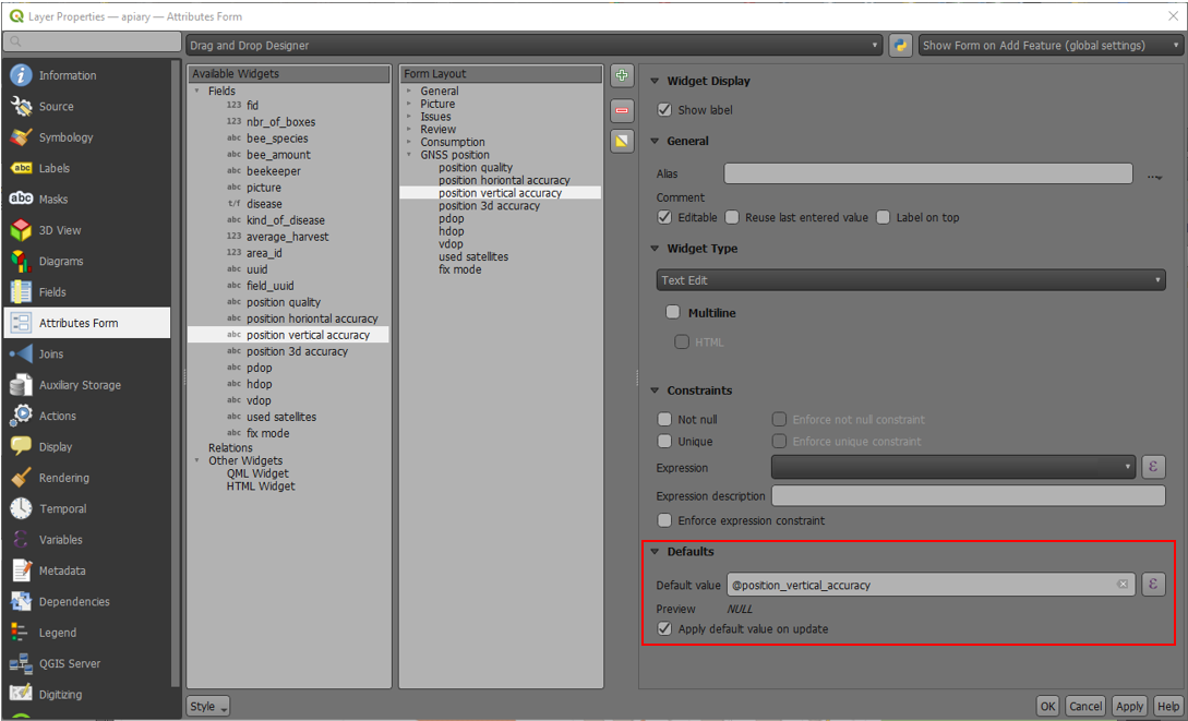
These variables are commonly used as part of default values expressions for fields to keep track of the quality of individual measured points.
A common use case is recording the horizontal accuracy, which can be done by using the variable @position_horizontal_accuracy.
Another often used strategy is using the altitude of the current measurement which can be achieved with z(@position_coordinate).
For a complete listing of all available variables, refer to the expression variables reference documentation.
Information for GNSS Z value with Vertical grid shift in use: - Antenna height compensation=False
| Vertical Grid Shift in use | point Z Value z(geometry) | GNSS Device z(@position_coordinate) | QField Display | QField Label |
|---|---|---|---|---|
| None | Z ellipsoidal device value | Z ellipsoidal device value | Z ellipsoidal device value | Altitude: xxx.xxxx m |
| Orthometric from device | Z orthometric device value | Z orthometric device value | Z orthometric device value | Altitude: xxx.xxxx m (ortho.) |
| USER_Shift_Grid.GTX vertical grid shift |
Z shiftgrid value | Z ellipsoidal device value | Z shiftgrid value | Altitude: xxx.xxxx m (grid) |
Vertex log layer
It is good practice to create a log layer of the collected vertices. It enables you to keep track of the meta data for each vertex like GNSS quality attributes and more.
Setup
-
Add a point layer to the project and attributes configured to store this information.
-
Assign the role digitizing logger to a point layer.
-
Go to > Project > Properties... > QField.
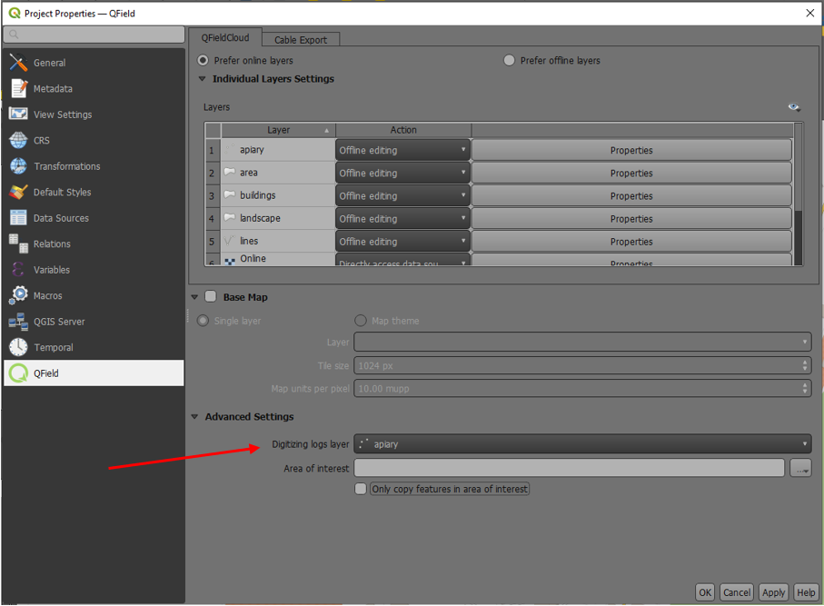
-
Set default values to the attributes using the positioning variables mentioned above.